The drivetrain was a 4 motor holonomic drive. It had forks on the front that flipped the different objects a basket that would dump everything over the wall at the last second, thus getting many points, and making it hard for the other teams into through them back over.
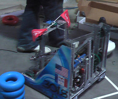
2009-2010 Clean Sweep
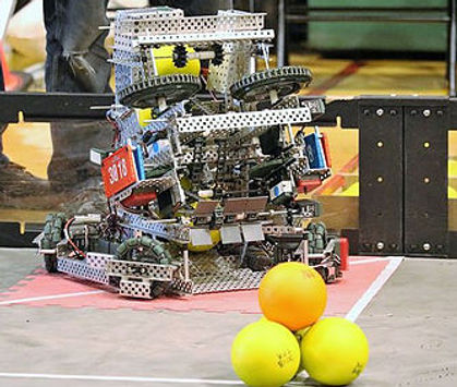
B.E.A.S.T.

2010-2011 Round Up
Sheila
She had a 6 motor chain drive, mounted to this was the low post alignment device that would help the driver line up with the low goals. She also had a high post alignment device that would line up with the high goal, but it would also flip off one tube off the goal. She had a tube-cage intake that could go over that back, due to her 270° gear rotation. The basket had an extension that enabled us to get up to twelve tubes at a time when we previously could only get eight. This is what also helped us get the Innovate Award at worlds.
2011-2012 Gateway
Andy
His drivetrain was a holonomic drive, built on an H-shaped frame. The frame was very minimalistic, making it easy for the four high-speed motors to power.
He had a symmetrical linear slide lift; that was powered by four low-strength motors running the chain via a single drive shaft. The drive shaft helped keep both sides in sync. The lift was attached to to the intake, that was tilted in between Nationals and Worlds. This made it so we could pick up more objects, and so we could reach the high goal easier.


He had a four-bar linkage lift with eight-inch arms. It was driven by two high-strength 393 motors geared down, with a ratio of about 11:1. On his Spatula, he had two high-strength 393-motors. His motors were chained 3:1 for torque. The spatula was made of a 16 x 6-inch piece of polycarbonate, and it scooped and threw sacks onto his table/conveyor. It was able to scoop up 4 sacks in less than a second and was approximately the width of 3 sacks.
His table carried the sacks on a 12×13 inch conveyor belt. His spatula tossed the sacks onto the table and his lift brought it up
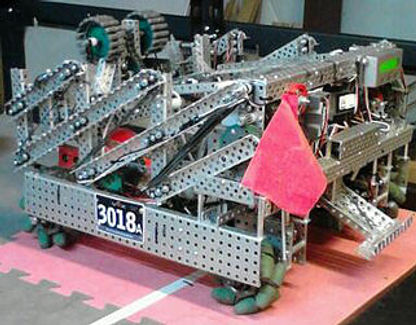
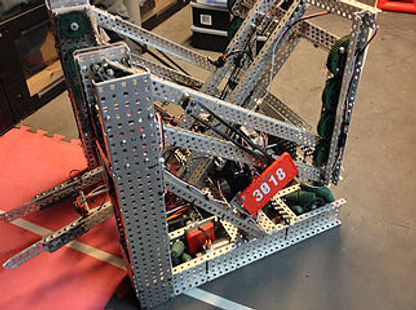
2012-2013 Sack Attack
Theta
to the trough. The table had a conveyor belt made of 5 high-strength tracks driven by one high-speed 393 motor. His descorer had “teeth” (standoffs) that pulled sacks from the trough. It was mounted on his counter-balance bar (very far back on me) so that the sacks fell onto the conveyor. The descorer was driven by a high-strength 393 motor.
He could easily mecanum wheels. Each wheel is driven by a high-speed 393 motor. These keep him from being easily pushed around from the side. Also, they allowed him to strafe left and right, which was very nice when he scored into the trough, and when he picked up sacks along the walls.
Nora
2013-2014 Toss Up
Nora had a four-wheel drive that was powered by six, 393 motors that are geared to high speed. She had mecanum wheels so she could strafe from side to side. She had an eight-bar linkage lift, powered by two 393 high strength motors that were externally geared 1:10, and could lift in about two seconds. She had a flip-out, top-roller intake, that used tank tread traction links to intake the buckyballs with ease.
After the roller flipped down, a passive latch kept it from going back up. The roller needed a wall
to grab the large balls. Her hopper, the lexan with a decal, was mountedat about a 20-degree angle and could hold up to three buckyballs or one large ball. Nora could dump out three buckyballs in about 2 seconds. Because of the height she got when fully lifted, she could easily tip over, so we added a wheelie bar to keep her upright. We wanted to be able to fling the beach balls so we added a pneumatic powered flipper that could shoot the balls from the hanging zone to the scoring zone.
2014-2015 Skyrise
Delta
He had a four mecanum wheel drive, each powered by a 393 high-speed motor. The back two wheels were directly driven, and the front two were chained, using 18 tooth sprockets.
We had decided to try a double reverse four bar lift. It was powered by six 393 motors geared to high speed with an external 12-18 gear reduction. We chose this lift because it allowed the intake to move in a linear fashion, using up less space and making it easier to drive. The four-bar linkages make the design fairly simple.
Delta’s intake was a two prong, pneumatic powered, forward facing intake. In order to pick up cubes, you drove forward and skewered the cube through the middle with the prongs. It didn’t fit very well going into the cube while it is open, so you had to close the intake for it to work correctly. For the sky rise pieces, you had to straddle the sky rise piece when it is in the holder, then lift, and it slid out of the holder.
Delta 2.0
Delta 2.0's drivetrain had four mecanum wheels, each powered by a 393 high-speed motor. Using mecanum wheels gave us the ability to strafe from side to side as well as go forward and backward. All of the wheels were directly driven. The wheels were mounted at the four corners of Delta for maximum stability.
The lift was a double reverse six bar lift with the upper six bar modified so that the intake chain was embedded into the long bar. This gave us more height and better power efficiency as the weight of the cubes was centered over the chassis of the robot and closer to the rotation point of the robot.
The cube intake was a vertical passive intake that was also the support beam for our Skyrise intake. It had standoffs sticking out which we hooked the cubes on to keep them horizontal, which made scoring them a lot easier. It started out folded up so it fit in the 18 by 18 size restraints and then it flipped out for use.
We had a device that was solely used for skyrise pieces, which was mounted to the front of the robot for the best rotation point. It was mounted so that we could park in between the skyrise loader and the base. Using this method we were able to score without having to move, by swinging back and forth picking up and scoring skyrises quickly and efficiently. The swing arm was powered by a 393 motor which was geared three to five. The claw was pneumatically powered, as we didn't have any more motors to spare. For the claw, we modified the tread wheels from our old mecanum wheels to become rollers to pick up the skyrise pieces easier.
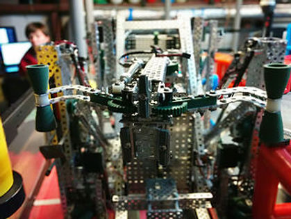
Ordu had a modified holonomic drive, that used 4 omni wheels placed at a 63 degree angle. The wheels were positioned in a 3-4-5 triangle. Because it is still a right triangle, and each wheel was perpendicular to another wheel we were allowed to still go forward and backwards. When omni wheels are so positioned, they act like mecanum wheels, which allowed us to strafe side to side as well as being much lighter. The intake was divided into two different stages.
The first part of the intake grabed the balls using three sprockets with flaps, with the third sprocket moving the balls to the second stage. This next section used a running chain that pressed the ball
Ordü
2015-2016 Nothing But Net
against the ramp and took it to the launcher. The advantage to having this two part intake was that we were able to grab the balls and pull them into the next section anywhere on the field, store and then launch them in a more efficient way.
After being fed to the top of our intake, the ball was placed in between two spinners and launched across the field. The spinners were made with basic wheels that are 5 inches in diameter, with chain wrapped around each, which increased the pressure on the balls and gave it more force and accuracy. The spinners were mounted at a 37* degree angle to give us the proper trajectory that we needed. The deflector was put on the him for short ranged shooting. Powered by a small motor, it fliped out, and the balls, launched at a slower speed, then slid up the deflector into the net.
This robot was expected to be extremely quick. The goal was for the robot to drive around and clear the field by using a Wheel powered brake lift: This idea used the wheels, and then used a break system to launch the balls using momentum. The launcher would be a launch pad type surface, and would brake the wheels using pneumatic pistons, attached to the launch pad there was going to be a lever, which would use the wheel’s momentum to launch the balls through a funnel directed towards the goal. Kaos was going to be a ramp type intake, which would feed balls into a launch plate that was the lever. When we wanted to launch balls we would activate a pneumatic brake system to clamp on the wheels and shove the launch pad into the ground, thus transferring the momentum of the robot to the launch pad launching all balls in the robot to be flung forward towards the goal. While this wasn't going to be the most accurate robot, we were hoping that later in the competition it would be a valuable asset to other better teams.
Due to technical difficulties we were never able to complete our goal but we did end up designing and building the fastest robot in robotics up to this point. Through the process of building him,we learned that it is possible to go so fast that you can't transfer enouhg energy to launch the balls anywhere.
Kaos Theory
2016-2017 Starstruck
Luna

The drivetrain was designed for strafing. It was a straight drive with four mecanum wheels, each powered by a high-speed motor. There were two smaller omni-wheels in the back mounted on a linear slide powered by pneumatics on the drivetrain for extra stability.
The lift consisted of six high-strength motors with a 1:5 gear ratio, powered by 3 motors. A high strength axle was used to make sure both sides of the lift went up at the same time.
Our claw was designed to dump stars and cubes backwards. It consisted of two full length c-channels with shorter c-channels tapered at end to help us grab
stars and cubes quickly by pulling them in.
The dispersion bar was a unique mechanism, mounted on a hinge on our claw. We had decided that in a match, it's more important to just get the stars on the other side and not necessarily in the far zone so we only used the dispersion bar in skills. It was designed to throw stars and cubes to the far zone and scatter them, which made it harder for opponents to collect and throw back over.
Our drivetrain was made of 6 omni-wheels. The front 4 were powered by 393 high-speed motors and were mounted on the robot's center of mass. Holding game objects outside of our robot made our center of mass move outward so our drivetrain had to move with it.
Our lift was a simple two-bar, powered by 8 high-strength 393 motors. It had a gear ratio of 3:5 with 4 motors on each side. We wrapped bungee around 2 cam gears to let it act as a tensioner.
Our fork consisted of 4 C-channels, with axles extending out, attached to an L-bracket. The fork was attached to the arms of the lift with 3 hinges. The outside axles had a collar at the very end to prevent getting stuck under the wall. We also had a locking mechanism to keep the fork from flopping up and down when we were launching the elements. There were two longer c-channels that extend down and were attached to small wheels. We made a locking mechanism that hooked onto the lift so when it went up the latch was released and the wheelie bar was deployed using bungee.
Polaris
2017-2018 In The Zone
The drivetrain had four 3.75” omni wheels powered by 4 high-speed motors on a U-shaped chassis. We used a straight drive to give is more power and speed. The high speed motors also gave our robot an edge in the speed battle, which we felt was important for this competition. The drivetrain was very stable and well supported since it was the foundation of our robot. We also had 2 optical shaft encoders on each rear wheel. The encoder was mounted to the drivetrain and driven with mini chain to the rear wheel. This helped us achieve more accurate autonomous routines.
The lift system we used was a two stage scissor lift. It was powered by four high-speed motors on a 7:1 gear ratio. It had a high-strength shaft with a 36-tooth gear on each end connecting it to the 12 tooth gear on the lift. This connected both sides of the lift together, which kept the lift in sync. In the middle of the first stage there was a three wide c-channel used as a cross brace. On the bottom of the first stage were steel slides that the c-channels slid back and forth on when the lift went up and down. This was quite unique as we did not use the typical pieces found on a linear slide.1 After much experimentation, we decided that this was the system that created the least amount of friction
At the top of the lift was a four bar swing arm, powered by a high-speed motor with a 1:5 gear ratio. To prevent it from getting out of sync, we used a solid shaft running through both sides of the swing arm. We used the swing arm to pick up cones and place them on mobile bases. We used a potentiometer and a limit switch to set preset heights and monitor its position which helped to pick up cones and score them.
A base lifter is a device used to pick up, move and then drop off the mobile bases on the field. Our base lifter was powered by 2 high-speed motors on a 1:5 gear ratio to give us both speed and strength. We used a 4 bar because it gave us the power and angles we needed.
The intake was a double roller intake featuring four 24 tooth sprockets that rotate opposite each other to intake or outake cones. We used beveled edge gears to most efficiently power it using 1 motor.
2019-2020 Tower Takeover
Jammal
This robot has a 6 wheel U drive with the a motor for each of the back wheels and a motor for 2 each of the front wheels. Are robot is a tray bot with treads around gears to bring the cubes up into the tray, it is able to score nine in the corner, and put cubes in the low and medium towers. They tray has bracing to make sure that the cubes don't twist when they are going up the tray. The robot scores cubes into the cups by lifting up the intake arms to score.
